
Type
- Menu: 4.4.12-1.1
Description
Specifies the reference travel type to be used for referencing.
The following settings are possible:
Setting | Meaning |
|---|---|
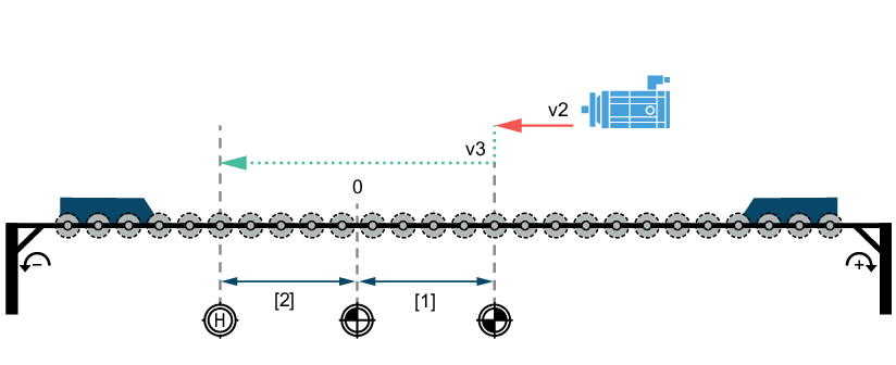
Zero pulse – negative direction | With this reference travel type, referencing is always performed to the zero pulse (reference pulse of the encoder) irrespective of what is set in the Reference to zero pulse parameter. The first search direction is negative. The reference point is the first zero pulse. A reference cam is not required. |
Reference travel starts in the negative direction of rotation at Retraction speed [v2] up to the reference point.
If the parameter Go to home position is set to 1 (Yes), the drive moves from the reference point to the home position at Homing speed [v3].

| Reference point |
| Machine zero |
| Home position (optional) |
| Hardware limit switches |
v2 | Travel to the reference point at Retraction speed [v2] |
v3 | Travel to the home position at Homing speed [v3] |
[1] | Reference offset (distance between reference point and machine zero) |
[2] | Distance between machine zero and home position |


Setting | Meaning |
|---|---|
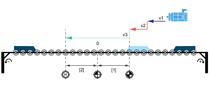
Reference cam – negative end | With this reference travel type, referencing is performed to the negative end of the reference cam. The first search direction is negative. The following reference travel configurations can be made:
|
The start position of the drive is to the right of the reference cam. Reference travel starts in negative direction of rotation at Search speed [v1] up to the positive end of the reference cam. As soon as the reference cam is detected, the drive moves at Retraction speed [v2] in negative direction up to the reference point.
The parameter Reference to zero pulse is set to 0 (No) (referencing to zero pulse). The reference point is the falling edge at the negative end of the reference cam.
If the parameter Go to home position is set to 1 (Yes), the drive moves from the reference point to the home position at Homing speed [v3].

| Reference point |
| Machine zero |
| Home position (optional) |
| Hardware limit switches |
| Reference cam |
v1 | Travel to reference cam at Search speed [v1] |
v2 | Travel to the reference point at Retraction speed [v2] |
v3 | Travel to the home position at Homing speed [v3] |
[1] | Reference offset (distance between reference point and machine zero) |
[2] | Distance between machine zero and home position |

The start position of the drive is to the left of the reference cam. Reference travel starts in negative direction of rotation at Search speed [v1] up to the negative hardware limit switch. As soon as the limit switch is detected, the drive turns and referencing is continued in positive direction of rotation up to the negative end of the reference cam. After the reference cam is detected, the drive turns on the reference cam and travels to the reference point in negative direction of rotation at Retraction speed [v2].
The parameter Reference to zero pulse is set to 0 (No) (referencing to zero pulse). The reference point is the falling edge at the negative end of the reference cam.
If the parameter Go to home position is set to 1 (Yes), the drive moves from the reference point to the home position at Homing speed [v3].

| Reference point |
| Machine zero |
| Home position (optional) |
| Hardware limit switches |
| Reference cam |
v1 | Travel to reference cam at Search speed [v1] |
v2 | Travel to the reference point at Retraction speed [v2] |
v3 | Travel to the home position at Homing speed [v3] |
[1] | Reference offset (distance between reference point and machine zero) |
[2] | Distance between machine zero and home position |
The start position of the drive is to the right of the reference cam. Reference travel starts in negative direction of rotation at Search speed [v1] up to the positive end of the reference cam. As soon as the reference cam is detected, the drive moves at Retraction speed [v2] in negative direction up to the reference point.
The parameter Reference to zero pulse is set to 1 (Yes) (referencing to zero pulse). The reference point is the first zero pulse (reference pulse of the encoder) after the falling edge at the negative end of the reference cam.
If the parameter Go to home position is set to 1 (Yes), the drive moves from the reference point to the home position at Homing speed [v3].

| Reference point |
| Machine zero |
| Home position (optional) |
| Hardware limit switches |
| Reference cam |
v1 | Travel to reference cam at Search speed [v1] |
v2 | Travel to the reference point at Retraction speed [v2] |
v3 | Travel to the home position at Homing speed [v3] |
[1] | Reference offset (distance between reference point and machine zero) |
[2] | Distance between machine zero and home position |
The start position of the drive is to the left of the reference cam. Reference travel starts in negative direction of rotation at Search speed [v1] up to the negative hardware limit switch. As soon as the limit switch is detected, the drive turns and referencing is continued in positive direction of rotation up to the negative end of the reference cam. After the reference cam is detected, the drive turns on the reference cam and travels to the reference point in negative direction of rotation at Retraction speed [v2].
The parameter Reference to zero pulse is set to 1 (Yes) (referencing to zero pulse). The reference point is the first zero pulse (reference pulse of the encoder) after the falling edge at the negative end of the reference cam.
If the parameter Go to home position is set to 1 (Yes), the drive moves from the reference point to the home position at Homing speed [v3].

| Reference point |
| Machine zero |
| Home position (optional) |
| Hardware limit switches |
| Reference cam |
v1 | Travel to reference cam at Search speed [v1] |
v2 | Travel to the reference point at Retraction speed [v2] |
v3 | Travel to the home position at Homing speed [v3] |
[1] | Reference offset (distance between reference point and machine zero) |
[2] | Distance between machine zero and home position |
Setting | Meaning |
|---|---|
Reference cam – positive end | With this reference travel type, referencing is performed to the positive end of the reference cam. The first search direction is positive. The following reference travel configurations can be made:
|
The start position of the drive is to the left of the reference cam. Reference travel starts in positive direction of rotation at Search speed [v1] up to the negative end of the reference cam. As soon as the reference cam is detected, the drive moves at Retraction speed [v2] in positive direction of rotation up to the reference point.
The parameter Reference to zero pulse is set to 0 (No) (reference without zero pulse). The reference point is the falling edge at the positive edge of the reference cam.
If the parameter Go to home position is set to 1 (Yes), the drive moves from the reference point to the home position at Homing speed [v3].

| Reference point |
| Machine zero |
| Home position (optional) |
| Hardware limit switches |
| Reference cam |
v1 | Travel to reference cam at Search speed [v1] |
v2 | Travel to the reference point at Retraction speed [v2] |
v3 | Travel to the home position at Homing speed [v3] |
[1] | Reference offset (distance between reference point and machine zero) |
[2] | Distance between machine zero and home position |
The start position of the drive is to the right of the reference cam. Reference travel starts in positive direction of rotation at Search speed [v1] up to the positive hardware limit switch. As soon as the limit switch is detected, the drive turns and referencing is continued in negative direction of rotation up to the positive end of the reference cam. After the reference cam is detected, the drive turns on the reference cam and travels to the reference point in positive direction of rotation at Retraction speed [v2].
The parameter Reference to zero pulse is set to 0 (No) (reference without zero pulse). The reference point is the falling edge at the positive edge of the reference cam.
If the parameter Go to home position is set to 1 (Yes), the drive moves from the reference point to the home position at Homing speed [v3].

| Reference point |
| Machine zero |
| Home position (optional) |
| Hardware limit switches |
| Reference cam |
v1 | Travel to reference cam at Search speed [v1] |
v2 | Travel to the reference point at Retraction speed [v2] |
v3 | Travel to the home position at Homing speed [v3] |
[1] | Reference offset (distance between reference point and machine zero) |
[2] | Distance between machine zero and home position |
The start position of the drive is to the left of the reference cam. Reference travel starts in positive direction of rotation at Search speed [v1] up to the negative end of the reference cam. As soon as the reference cam is detected, the drive moves at Retraction speed [v2] in positive direction of rotation up to the reference point.
The parameter Reference to zero pulse is set to 1 (Yes) (referencing to zero pulse). The reference point is the first zero pulse (reference pulse of the encoder) after the falling edge at the positive end of the reference cam.
If the parameter Go to home position is set to 1 (Yes), the drive moves from the reference point to the home position at Homing speed [v3].

| Reference point |
| Machine zero |
| Home position (optional) |
| Hardware limit switches |
| Reference cam |
v1 | Travel to reference cam at Search speed [v1] |
v2 | Travel to the reference point at Retraction speed [v2] |
v3 | Travel to the home position at Homing speed [v3] |
[1] | Reference offset (distance between reference point and machine zero) |
[2] | Distance between machine zero and home position |
The start position of the drive is to the right of the reference cam. Reference travel starts in positive direction of rotation at Search speed [v1] up to the positive hardware limit switch. As soon as the limit switch is detected, the drive turns and referencing is continued in negative direction of rotation up to the positive end of the reference cam. After the reference cam is detected, the drive turns on the reference cam and travels to the reference point in positive direction of rotation at Retraction speed [v2].
The parameter Reference to zero pulse is set to 1 (Yes) (referencing to zero pulse). The reference point is the first zero pulse (reference pulse of the encoder) after the falling edge at the positive end of the reference cam.
If the parameter Go to home position is set to 1 (Yes), the drive moves from the reference point to the home position at Homing speed [v3].

| Reference point |
| Machine zero |
| Home position (optional) |
| Hardware limit switches |
| Reference cam |
v1 | Travel to reference cam at Search speed [v1] |
v2 | Travel to the reference point at Retraction speed [v2] |
v3 | Travel to the home position at Homing speed [v3] |
[1] | Reference offset (distance between reference point and machine zero) |
[2] | Distance between machine zero and home position |
Setting | Meaning |
|---|---|
Limit switch positive | With this reference travel type, referencing is performed to the positive hardware limit switch. The first search direction is positive. A reference cam is not required. The following reference travel configurations can be made:
|
Reference travel starts in positive direction of rotation at Search speed [v1] up to the positive hardware limit switch. As soon as the limit switch is detected, the drive turns and travels to the reference point in negative direction of rotation at Retraction speed [v2].
The Reference to zero pulse parameter is set to 0 (No) (referencing without zero pulse). The reference point is the edge at the positive limit switch.
If the parameter Go to home position is set to 1 (Yes), the drive moves from the reference point to the home position at Homing speed [v3].
If the limit switches are swapped, fault E‑29.4 HW limit switches: Limit switches swapped is triggered.

| Reference point |
| Machine zero |
| Home position (optional) |
| Hardware limit switches |
v1 | Travel to reference cam at Search speed [v1] |
v2 | Travel to the reference point at Retraction speed [v2] |
v3 | Travel to the home position at Homing speed [v3] |
[1] | Reference offset (distance between reference point and machine zero) |
[2] | Distance between machine zero and home position |
Reference travel starts in positive direction of rotation at Search speed [v1] up to the positive hardware limit switch. As soon as the limit switch is detected, the drive turns and travels to the reference point in negative direction of rotation at Retraction speed [v2].
The Reference to zero pulse parameter is set to 1 (Yes) (referencing to zero pulse). The reference point is the first zero pulse (reference pulse of the encoder) after the edge at the positive limit switch.
If the parameter Go to home position is set to 1 (Yes), the drive moves from the reference point to the home position at Homing speed [v3].
If the limit switches are swapped, fault E‑29.4 HW limit switches: Limit switches swapped is triggered.

| Reference point |
| Machine zero |
| Home position (optional) |
| Hardware limit switches |
v1 | Travel to reference cam at Search speed [v1] |
v2 | Travel to the reference point at Retraction speed [v2] |
v3 | Travel to the home position at Homing speed [v3] |
[1] | Reference offset (distance between reference point and machine zero) |
[2] | Distance between machine zero and home position |
Setting | Meaning |
|---|---|
Limit switch negative | With this reference travel type, referencing is performed to the negative hardware limit switch. The first search direction is negative. A reference cam is not required. The following reference travel configurations can be made:
|
Reference travel starts in negative direction of rotation at Search speed [v1] up to the negative hardware limit switch. As soon as the limit switch is detected, the drive turns and travels to the reference point in positive direction at Retraction speed [v2].
The Reference to zero pulse parameter is set to 0 (No) (referencing without zero pulse). The reference point is the edge at the negative limit switch.
If the parameter Go to home position is set to 1 (Yes), the drive moves from the reference point to the home position at Homing speed [v3].
If the limit switches are swapped, fault E‑29.4 HW limit switches: Limit switches swapped is triggered.

| Reference point |
| Machine zero |
| Home position (optional) |
| Hardware limit switches |
v1 | Travel to reference cam at Search speed [v1] |
v2 | Travel to the reference point at Retraction speed [v2] |
v3 | Travel to the home position at Homing speed [v3] |
[1] | Reference offset (distance between reference point and machine zero) |
[2] | Distance between machine zero and home position |
Reference travel starts in negative direction of rotation at Search speed [v1] up to the negative hardware limit switch. As soon as the limit switch is detected, the drive turns and travels to the reference point in positive direction at Retraction speed [v2].
The Reference to zero pulse parameter is set to 1 (Yes) (referencing to zero pulse). The reference point is the first zero pulse (reference pulse of the encoder) after the edge at the negative limit switch.
If the parameter Go to home position is set to 1 (Yes), the drive moves from the reference point to the home position at Homing speed [v3].
If the limit switches are swapped, fault E‑29.4 HW limit switches: Limit switches swapped is triggered.

| Reference point |
| Machine zero |
| Home position (optional) |
| Hardware limit switches |
v1 | Travel to reference cam at Search speed [v1] |
v2 | Travel to the reference point at Retraction speed [v2] |
v3 | Travel to the home position at Homing speed [v3] |
[1] | Reference offset (distance between reference point and machine zero) |
[2] | Distance between machine zero and home position |
Setting | Meaning |
|---|---|
Reference cam flush – limit switch positive | With this reference travel type, referencing is performed to reference cams. The reference cam must start just before or in line with the positive hardware limit switch and must project into the limit switch. Reference travel starts at search speed in positive direction. When the negative end of the reference cam is reached, the drive turns and leaves the reference cam again at retraction speed. If no reference cam is found in positive direction of rotation, a fault is triggered at the positive limit switch. If the positive limit switch is approached during the delay on the reference cam, it is ignored and referencing is continued. The following reference travel configurations can be made:
|
Reference travel starts in positive direction of rotation at Search speed [v1] up to the negative end of the reference cam. After detecting the reference cam, the drive decelerates with the Deceleration specified for reference travel. The drive turns and moves to the reference point in negative direction of rotation at Retraction speed [v2].
The Reference to zero pulse parameter is set to 0 (No) (referencing without zero pulse). The reference point is the falling edge at the negative end of the reference cam.
If the parameter Go to home position is set to 1 (Yes), the drive moves from the reference point to the home position at Homing speed [v3].
If the limit switches are swapped, fault E‑29.4 HW limit switches: Limit switches swapped is triggered.

| Reference point |
| Machine zero |
| Home position (optional) |
| Hardware limit switches |
| Reference cam |
v1 | Travel to reference cam at Search speed [v1] |
v2 | Travel to the reference point at Retraction speed [v2] |
v3 | Travel to the home position at Homing speed [v3] |
[1] | Reference offset (distance between reference point and machine zero) |
[2] | Distance between machine zero and home position |
Reference travel starts in positive direction of rotation at Search speed [v1] up to the negative end of the reference cam. After detecting the reference cam, the drive decelerates with the Deceleration specified for reference travel. The drive turns and moves to the reference point in negative direction of rotation at Retraction speed [v2].
The Reference to zero pulse parameter is set to 1 (Yes) (referencing to zero pulse). The reference point is the first zero pulse (reference pulse of the encoder) after the falling edge at the negative end of the reference cam.
If the parameter Go to home position is set to 1 (Yes), the drive moves from the reference point to the home position at Homing speed [v3].
If the limit switches are swapped, fault E‑29.4 HW limit switches: Limit switches swapped is triggered.

| Reference point |
| Machine zero |
| Home position (optional) |
| Hardware limit switches |
| Reference cam |
v1 | Travel to reference cam at Search speed [v1] |
v2 | Travel to the reference point at Retraction speed [v2] |
v3 | Travel to the home position at Homing speed [v3] |
[1] | Reference offset (distance between reference point and machine zero) |
[2] | Distance between machine zero and home position |
Setting | Meaning |
|---|---|
Reference cam flush – limit switch negative | With this reference travel type, referencing is performed to reference cams. The reference cam must start just before or in line with the negative hardware limit switch and must project into the limit switch. Reference travel starts at search speed in negative direction. When the positive end of the reference cam is reached, the drive turns and leaves the reference cam again at retraction speed. If no reference cam is found in negative direction of rotation, a fault is triggered at the negative limit switch. If the negative limit switch is approached during the delay on the reference cam, it is ignored and referencing is continued. The following reference travel configurations can be made:
|
Reference travel starts in negative direction of rotation at Search speed [v1] up to the positive end of the reference cam. After detecting the reference cam, the drive decelerates with the Deceleration specified for reference travel. The drive turns and moves to the reference point in positive direction of rotation at Retraction speed [v2].
The Reference to zero pulse parameter is set to 0 (No) (referencing without zero pulse). The reference point is the falling edge at the positive edge of the reference cam.
If the parameter Go to home position is set to 1 (Yes), the drive moves from the reference point to the home position at Homing speed [v3].
If the limit switches are swapped, fault E‑29.4 HW limit switches: Limit switches swapped is triggered.

| Reference point |
| Machine zero |
| Home position (optional) |
| Hardware limit switches |
| Reference cam |
v1 | Travel to reference cam at Search speed [v1] |
v2 | Travel to the reference point at Retraction speed [v2] |
v3 | Travel to the home position at Homing speed [v3] |
[1] | Reference offset (distance between reference point and machine zero) |
[2] | Distance between machine zero and home position |
Reference travel starts in negative direction of rotation at Search speed [v1] up to the positive end of the reference cam. After detecting the reference cam, the drive decelerates with the Deceleration specified for reference travel. The drive turns and moves to the reference point in positive direction of rotation at Retraction speed [v2].
The Reference to zero pulse parameter is set to 1 (Yes) (referencing to zero pulse). The reference point is the first zero pulse (reference pulse of the encoder) after the falling edge at the positive end of the reference cam.
If the parameter Go to home position is set to 1 (Yes), the drive moves from the reference point to the home position at Homing speed [v3].
If the limit switches are swapped, fault E‑29.4 HW limit switches: Limit switches swapped is triggered.

| Reference point |
| Machine zero |
| Home position (optional) |
| Hardware limit switches |
| Reference cam |
v1 | Travel to reference cam at Search speed [v1] |
v2 | Travel to the reference point at Retraction speed [v2] |
v3 | Travel to the home position at Homing speed [v3] |
[1] | Reference offset (distance between reference point and machine zero) |
[2] | Distance between machine zero and home position |
Setting | Meaning |
|---|---|
Referencing without reference travel | With this reference travel type, referencing is performed to the current position at the time when the drive function is activated. No check is performed to determine whether the drive is stopped. This reference travel type can be used, for example, to determine a relative movement since the last reference travel. If the drive function is selected, the drive stops subject to speed control with the Deceleration determined for reference travel. The drive remains in this state until the drive function is finished. NOTE: This reference travel type can also be performed if an FCB with higher priority than FCB 12 is active. For example, if the axis signals Not ready, a fault response is currently being performed, or the output stage is disabled for other reasons. For referencing, a rising edge must be detected when the reference travel is requested via a digital input or via a bit of the status words. |


CAUTION

Any hardware limit switches connected to the inverter will be ignored in this reference travel configuration.
Risk of jamming and crushing.
- Make sure that traveling beyond the limit switch is permitted.
Setting | Meaning |
|---|---|
Fixed stop positive | With this reference travel type, referencing is performed to a fixed stop. The system must be designed in such a way that the fixed stop withstands the impact of the respective speed without being damaged. The search direction is positive. The reference point is the positive fixed stop. The setting of the Reference to zero pulse parameter is ignored. The following reference travel configurations can be made:
|
If the Speed changeover before fixed stop parameter is set to None, reference travel starts in the positive direction of rotation with Retraction speed [v2] and Torque limit fixed stop up to the reference point. The reference point is the positive fixed stop.
If the parameter Go to home position is set to 1 (Yes), the drive moves from the reference point to the home position at Homing speed [v3].
The parameter Dwell time at fixed stop is used to specify how long the drive must be at standstill until the reference point is adopted.

| Reference point |
| Machine zero |
| Home position (optional) |
| Fixed stop |
v2 | Travel to the reference point at Retraction speed [v2] |
v3 | Travel to the home position at Homing speed [v3] |
[1] | Reference offset (distance between reference point and machine zero) |
[2] | Distance between machine zero and home position |

If the parameter Speed changeover before fixed stop is set to HW limit switch, the hardware limit switch must be flush with the fixed stop or protrude into the fixed stop.
SEW‑EURODRIVE recommends to set a homing run in the referencing. Else, the reference travel ends in the limit switch.
Reference travel starts in the positive direction of rotation with Search speed [v1] and the torque limit active outside of the reference travel up to the positive limit switch. Upon detection of the limit switch, the drive travels up to the reference point in the positive direction of rotation with Retraction speed [v2] and Torque limit fixed stop. The reference point is the positive fixed stop.
If the parameter Go to home position is set to 1 (Yes), the drive moves from the reference point to the home position at Homing speed [v3].
The parameter Dwell time at fixed stop is used to specify how long the drive must be at standstill until the reference point is adopted.

| Reference point |
| Machine zero |
| Home position (optional) |
| Hardware limit switches |
| Fixed stop |
v1 | Travel to reference cam at Search speed [v1] |
v2 | Travel to the reference point at Retraction speed [v2] |
v3 | Travel to the home position at Homing speed [v3] |
[1] | Reference offset (distance between reference point and machine zero) |
[2] | Distance between machine zero and home position |
If the parameter Speed changeover before fixed stop is set to Reference cam, the reference cam must be flush with the fixed stop or protrude into the fixed stop.
Reference travel starts in the positive direction of rotation with Search speed [v1] and the torque limit active outside of the reference travel up to the positive reference cam. Upon detection of the reference cam, the drive travels up to the reference point in the positive direction of rotation with Retraction speed [v2] and Torque limit fixed stop. The reference point is the positive fixed stop.
If the parameter Go to home position is set to 1 (Yes), the drive moves from the reference point to the home position at Homing speed [v3].
The parameter Dwell time at fixed stop is used to specify how long the drive must be at standstill until the reference point is adopted.

| Reference point |
| Machine zero |
| Home position (optional) |
| Reference cam |
| Fixed stop |
v1 | Travel to reference cam at Search speed [v1] |
v2 | Travel to the reference point at Retraction speed [v2] |
v3 | Travel to the home position at Homing speed [v3] |
[1] | Reference offset (distance between reference point and machine zero) |
[2] | Distance between machine zero and home position |
CAUTION
Any hardware limit switches connected to the inverter will be ignored in this reference travel configuration.
Risk of jamming and crushing.
- Make sure that traveling beyond the limit switch is permitted.
Setting | Meaning |
|---|---|
Fixed stop negative | With this reference travel type, referencing is performed to a fixed stop. The system must be designed in such a way that the fixed stop withstands the impact of the respective speed without being damaged. The search direction is negative. The reference point is the negative fixed stop. The setting of the Reference to zero pulse parameter is ignored. The following reference travel configurations can be made:
|
If the Speed changeover before fixed stop parameter is set to None, reference travel starts in the negative direction of rotation with Retraction speed [v2] and Torque limit fixed stop up to the reference point. The reference point is the negative fixed stop.
If the parameter Go to home position is set to 1 (Yes), the drive moves from the reference point to the home position at Homing speed [v3].
The parameter Dwell time at fixed stop is used to specify how long the drive must be at standstill until the reference point is adopted.

| Reference point |
| Machine zero |
| Home position (optional) |
| Fixed stop |
v2 | Travel to the reference point at Retraction speed [v2] |
v3 | Travel to the home position at Homing speed [v3] |
[1] | Reference offset (distance between reference point and machine zero) |
[2] | Distance between machine zero and home position |
If the parameter Speed changeover before fixed stop is set to HW limit switch, the hardware limit switch must be flush with the fixed stop or protrude into the fixed stop.
SEW‑EURODRIVE recommends to set a homing run in the referencing. Else, the reference travel ends in the limit switch.
Reference travel starts in the negative direction of rotation with Search speed [v1] and the torque limit active outside of the reference travel up to the negative limit switch. Upon detection of the limit switch, the drive travels up to the reference point in the negative direction of rotation with Retraction speed [v2] and Torque limit fixed stop. The reference point is the negative fixed stop.
If the parameter Go to home position is set to 1 (Yes), the drive moves from the reference point to the home position at Homing speed [v3].
The parameter Dwell time at fixed stop is used to specify how long the drive must be at standstill until the reference point is adopted.

| Reference point |
| Machine zero |
| Home position (optional) |
| Hardware limit switches |
| Fixed stop |
v1 | Travel to reference cam at Search speed [v1] |
v2 | Travel to the reference point at Retraction speed [v2] |
v3 | Travel to the home position at Homing speed [v3] |
[1] | Reference offset (distance between reference point and machine zero) |
[2] | Distance between machine zero and home position |
If the parameter Speed changeover before fixed stop is set to Reference cam, the reference cam must be flush with the fixed stop or protrude into the fixed stop.
Reference travel starts in the negative direction of rotation with Search speed [v1] and the torque limit active outside of the reference travel up to the negative reference cam. Upon detection of the reference cam, the drive travels up to the reference point in the negative direction of rotation with Retraction speed [v2]. The reference point is the negative fixed stop.
If the parameter Go to home position is set to 1 (Yes), the drive moves from the reference point to the home position at Homing speed [v3].
The parameter Dwell time at fixed stop is used to specify how long the drive must be at standstill until the reference point is adopted.

| Reference point |
| Machine zero |
| Home position (optional) |
| Reference cam |
| Fixed stop |
v1 | Travel to reference cam at Search speed [v1] |
v2 | Travel to the reference point at Retraction speed [v2] |
v3 | Travel to the home position at Homing speed [v3] |
[1] | Reference offset (distance between reference point and machine zero) |
[2] | Distance between machine zero and home position |

