FCB 12 Reference travel
- Menu: 4.4.12
Description
To perform positioning, a drive has to be referenced to a defined starting position (reference point) within the permitted travel section. From this reference point, positions such as machine zero can then be determined and approached. The machine zero serves as a reference point for absolute positioning.
Machine zero must be set once for absolute encoders during initial startup in order to match the displayed position with the reference system of the system. For encoder types without absolute position detection, machine zero must be set each time the inverter is restarted. Machine zero is defined as follows:

Several reference travel types are available for defining the reference point. When referencing to zero pulse (reference pulse of the encoder), to reference cams or hardware limit switches, note the following:
- The zero pulse can only be used as a reference point when the encoder has a zero pulse and the zero pulse track is connected to the inverter.
- When referencing to zero pulse, the C‑track of the encoder is monitored. If no zero pulse is detected within 2.5 encoder revolutions, an error is triggered and the drive is stopped.
- The zero pulse shifts if the motor is replaced.
- In order to reference reference cams, a bit of the digital inputs (parameter group Inputs/outputs > Basic unit/I/O card) or a bit of the control words (parameter group Setpoints > Control word.) must be parameterized to FCB 12 Reference travel – reference cam.
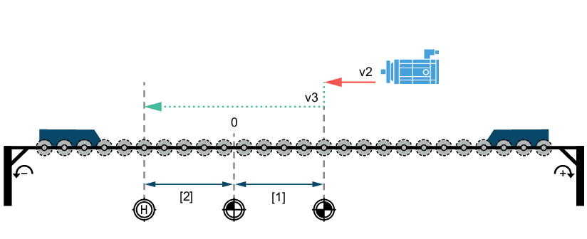
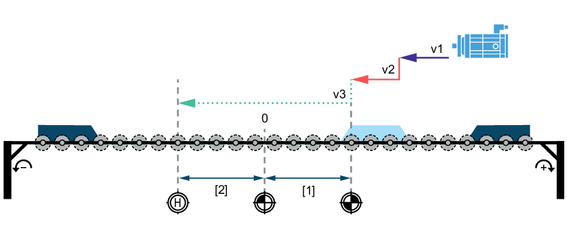
- For reference travel types that pass the reference cam, the reference cam length, acceleration, deceleration, search speed and retraction speed must be chosen in such a way that the drive at the reference cam can decelerate safely to the retraction speed. The end of the reference cam or the nearest zero pulse can be used as a reference point.
- For reference travel types with change of direction of rotation, the reference cam length, acceleration, deceleration, search speed and retraction speed must be chosen in such a way that the drive can turn safely on the reference cam and/or limit switch.
- If the zero pulse is exactly at the end of the reference cam when referencing to zero pulse, the falling edge of the reference cam before or after the zero pulse can be recorded as the reference point (switching hysteresis). As a result, the position of the reference point can vary by one motor revolution during subsequent reference travels. To prevent this inaccuracy, shift the reference cam by about the length of half a motor revolution.
- Unidirectional drives can only be referenced using a reference cam. For non-integer ratios, there is no fixed distance between the reference cam and zero pulse. In this case, set the end of the reference cam as the reference point.
- The reference cam can become inaccurate due to aging and wear or switching hysteresis.
- In order to reference hardware limit switches, a bit of the digital inputs (parameter group Inputs/outputs > Basic unit/I/O card) or a bit of the control words (parameter group Setpoints > Control word.) must be parameterized to HW limit switch positive or HW limit switch negative.
After referencing, homing can optionally be selected for each reference travel type. The drive is moved to a freely definable position independently of the reference point. As a result, the higher-level controller is no longer required to perform a positioning run.
If the inverter is switched off or an error is triggered, the Active drive referenced status bit is revoked. With absolute encoders, the status bit is always set and is only reset during a reference travel. However, if the reference travel is aborted, the status bit is not set.